
You can find these from different manufactures who use cheap parts and pretty labels all day long at quite an inflated cost. Often times boxes like I am about to show you how to make, assume that you are using it in your laundry room because they only come equipped with a 6 foot cord. Whatever, laundry rooms are not a place I would want to be working on anything. Including laundry. I digress frequently. Onward.
A high quality, professional and affordable way to tap into 240 volt home power.
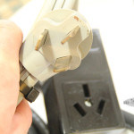
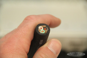
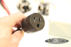
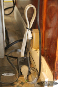
The 3 pong 240 volt plug and socket. NEMA 15-50r.
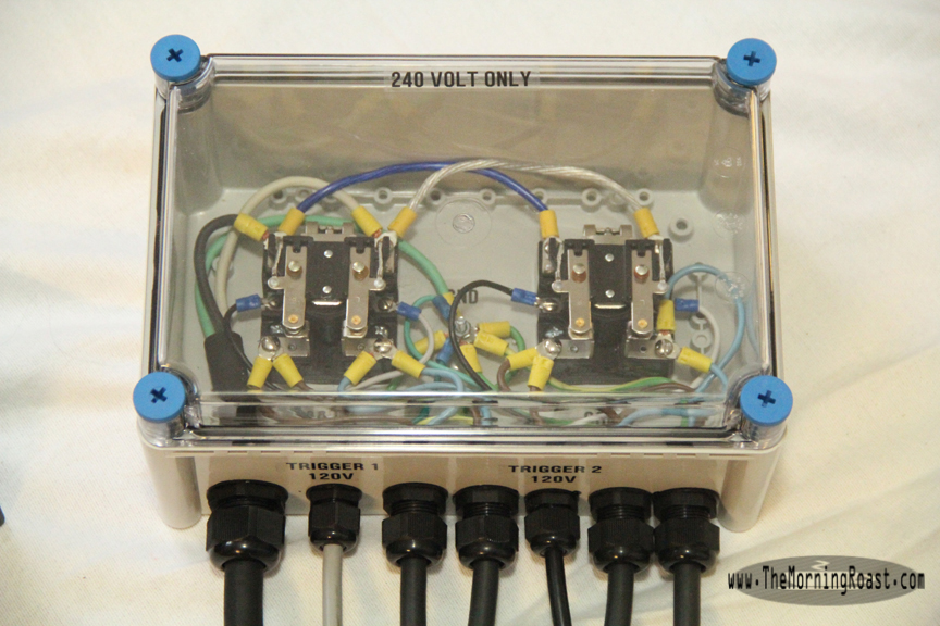
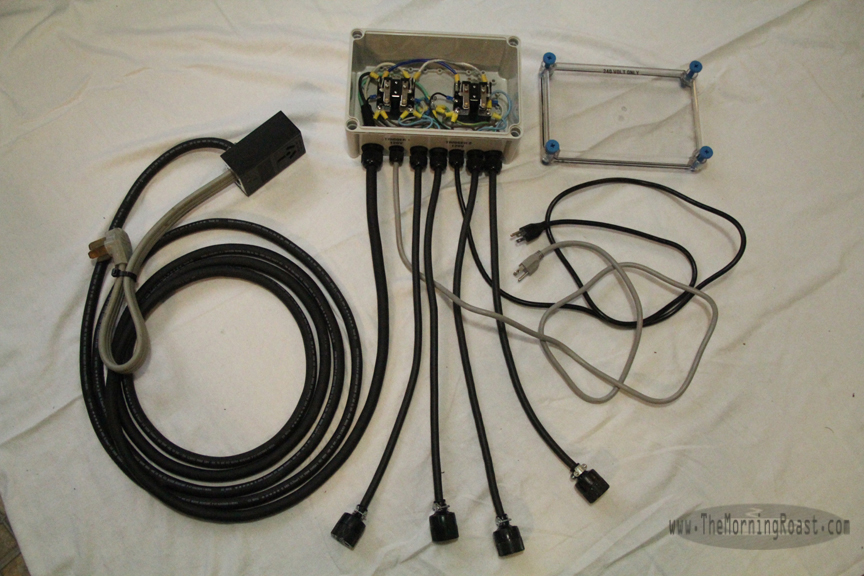
The unit I made allows me to plug into a NEMA 15-50R receptacle, which is a 240v 3 prong socket, found commonly for stoves and dryers. There is a short length of 10/3 wire that leads to another boxed 15-50r outlet, as well as a 20 foot 10/3 insulated cord at the end of which is the “power box”. Inside the box there are 2 DPST Relays (switches, contacts). That stands for “Dual Pole, Single Throw”, basically meaning 2 lanes of power turned on at the same time…
Each relay is powered independently by a 120v source, that can be plugged into any 120 volt outlet or timer. Each relay is capable of supplying loads of upto 30A at 240V, which combined is more than my breaker is rated for, but I would never max out the relays anyway. Just be aware of that. However, the relays themselves only require around a half an amp to be switched on, so there is very very little load being drawn from the 120v source or through your timers.
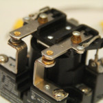
A Dual Pole Single Throw relay
The Power Box has 2 x 240V outputs per relay, each of which could supply upto 15a at 240 (which is the same wattage as 30A at 120v!). The benefits of this should be apparent. In total, the box has 4 outputs- 2 independently timed pairs of 240v outlets.
What this amounts to is the ability to run your laundry or stove, while remotely being able to power on one or more devices, such as drills, lathes, lights, and other equipment which is able to draw the higher voltage. Just be aware not to run the home appliance while running shop equipment as this may overload the breaker.
Similar boxes are upward of 450 dollars, and not made of nearly the same quality components. I have used American made relays, a NEMA rated poly enclosure, top quality conductors, etc. Not only does it look cool, but it was fun to make, and only cost about 120 bucks. It could have been 100 had I not gone with a clear top. 90 for a 10 foot cord version. If you don’t need the extra 15-50r outlet, maybe 80 bucks. Even cheaper still- use only one relay, depending on the load you are intending on running. Stop wasting hundos on stuff that ain’t fundo yo.
Here are some more pics and descriptions of how to do this.

Drilling holes to mount the relays
I use a drill bit slightly larger that the hardware to allow a little wiggle room to ease fitment.
Drilling holes for the power and trigger cords, and their respective keepers.
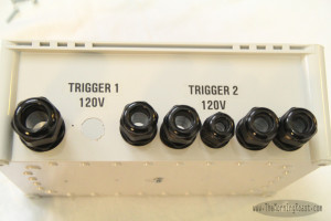
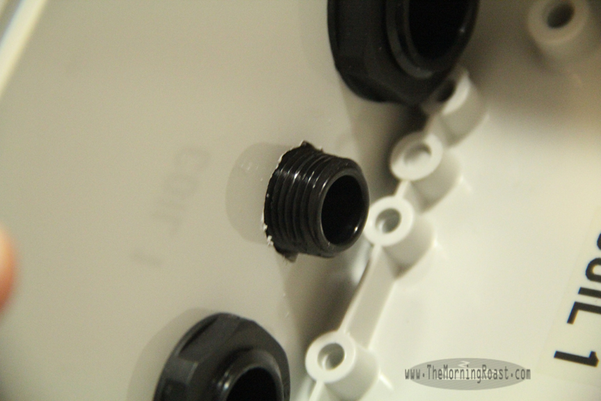
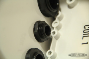
Here you can see we need 7 holes for this particular unit. One for the main 240 volt power supply coming in, which is on the left. This is a 10/3 supply line, and needed a 3/4 inch keeper. That required some opening up beyond my largest bit, as the keeper needs almost a 1 inch hole. From the left you then see an empty hole labelled “trigger 1, 120v”, and then 5 more keepers all set in place- another trigger, and the 4 x 240v switched outlets.
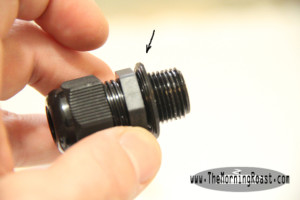
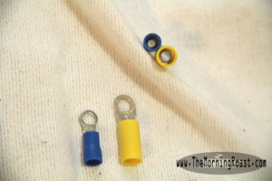
The keepers. Arrow points at rubber sealing washer.
Threaded end through the hole…
And thread the nut on the backside to hold it in place.
You will want to be sure to have all your holes drilled before you mount the relays, or start running cables. Just makes life much easier.
Easy way to measure the length of insulation you need to remove.
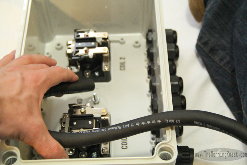
Here you can see that I have the relays secured in the box, and I begin to cut some wiring it up. In this shot I am approximating the length of insulation I need to cut away from the 10/3 to gain access to the wires inside. I like nice smooth bends that allow a little slack. This should help keep the connection joints stress free. And me too.
10/3 power wire. You can go as far as you need with this stuff.

Stripping back the 10/3. I cut away the paper.
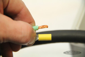
Stripping back the wires to receive a crimp ring terminal.
I always cut away about as much wire insulation as the length of the terminals colored insulator. A little more would be okay, but really, try not to go overboard.
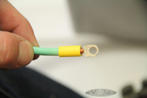
Perfect fit.
Notice not too much wire is sticking out the end near the ring. The green insulation is seated against the terminal inside the yellow insulator. The terminal is 10-14ga item.
Running the power supply cord.
Making the connection on one leg of the 240 volt relay.
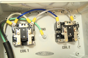
Connecting both relays with some jumpers.
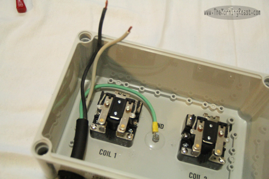
The jumpers I used ( the blue and white wires) made with short sections of 10ga. wire and some crimp terminals. This allows a nice clean installation of both relays. I ran the ground to a bolt in the middle of the box to make it an easy run for all 7 wires coming it.
Now that the power supply is connected I will be able to begin with the triggers and outputs. The triggers I used were just recycled appliance cords. I got lucky and found a black one and a gray one, so now the two will be easily distinguished. Which will be a handy feature, with all the cords I have!
12 volt trigger cords.
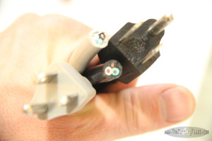
The 4 outlet cords are made of some nice 12/3 wire I had, and some NEMA 5-15R extension cord female ends. These are made for 120 use, but I am using them here for 240 to save on the cost of replacing the cord sets from my equipment. If you choose to do this, just be aware to never plug a 120 device into your outputs. Just because the plug will fit does not mean it will work. It will do damage- not play your stereo twice as loud.
NEMA 5-15r socket to be used for 240v outlet.
 So, if you are making one of these, at this point you have 6 more wires to run into the box and terminate. To the left you see a pic of all my cords pre stripped and ready for terminals. I used some yellow ones made for 10-14 gauge wire and blue ones for 12-16 gauge wire, as on my triggers.
There are a total of 7 ground wires that will secured to the post, so leave enough slack to ensure you are not packing them directly on top of one another, allowing the wires to run out at different angles.
Crimp ring size comparison.
Running a trigger wire, checking the length.
Do this with every wire, making sure it will reach it’s contact, and the ground. In this case, the ground is always the longest lead, so if it will reach there, you will be safe. Mark the sheath, cut it back and strip the ends.
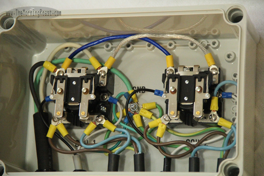
All connections are made. It may seem confusing, but it is very simple!
Maintain the ability to plug in the existing appliance.
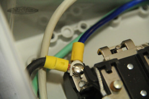
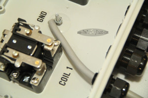
I try to make sure there are nice easy bends in all my wires. Note the ground post and all it’s connections. Ground is marked with the label “GND”. Now, this may seem confusing or like there are too many wires going all all over the place. But-
For each cable coming in, there are ONLY 3 connections. And luckily in this case, polarity does not matter. You can hook the relay triggers up however you want, and you can hook the 240 volt lines up however you want. All the grounds get connected together.
The white and black wire from the 240 are EACH supplying 120 volts. 120+120=240. The green is the ground. I used blue and clear wire to make my jumpers. Electricity doesn’t care what color the wire is, use whatever color you want, just keep you scheme consistent.
You may notice my triggers also use black, white and green wires. To keep a clean theme going, I wire them black to the left, white to the right.
For those of you paying attention, you may notice my outputs use a slightly different convention with brown, blue and green/yellow. That is fine by me, so I used brown to go with black and blue to go with white. The green and green/yellow became the ground.
The final product.
You can make your main tether as long or short as you want or need to. The outputs could be longer, or integrated into the box as wall style outlets. You could also use heavy duty extension cords, though that would most likely add to the cost. Not that it would matter much because you are saving a lot by making it how you like. If you wanted, you could integrate a timer directly into the design. For my purposes I plug my triggers into timers. If you wanted all 4 outputs could come from one relay, or you could use 4 relays each with one output and independent triggers. OR, you could share a trigger across several relays. You could use distribution blocks if you just wanted simple continuous non triggered power.
There are many ways you can configure a unit like this. If you have any questions, feel free to ask below. I check back frequently and will do my best to try and help. Thank you for reading.
Well another 1000W HPS make the difference. Thanks for the help!
You could easily add another 1000 watt to each of the relays, as long as the 240v source could handle the amps. I would stagger the triggers slightly, so as not to try to turn on a total of 6 1000w ballast in unison.
Thanks again for your contributions! Nice pictures too.
Thank you Rollitup! I should say the same to you folks!
How can I do 10 outlets with 5 relays??? Can I just chain them together like you did two???
Yes! Apologies for such delay in replying to your question. It was lost amongst a sea of spam linkers… In truth, with 5 relays and 10 outlets you have a lot of flexibility, depending on the loads that will be connected. The relays I used, were 30A (you should not run 30a continuously, no more than 70% to be safe) and have 2 1000w ballasts connected to them. They have been going for a year now, no troubles at all.
You could potentially connect 3 or 4 outlets to a single relay and then have some relays that control a single outlet. Just remember that each relay needs 120v timer controlled power and that the 240v source has the capacity to safely power all the devices you connected to the 10 outlets.